
Not sure dude. At this rate, maybe like another week or so. I have a bunch of voltage checks to go through before it can try to make sound. I'm not putting a tube in it until it passes all the tube-less tests.
Let's build an amp! Greg's journey to electrocution
Re: Let's build an amp! Greg's journey to electrocution
Rebel Yell

Re: Let's build an amp! Greg's journey to electrocution
Cool, I'm really impressed with this. Not just that your doing it and that it seems to be going well, but your whole methodical approach to it too.
Re: Let's build an amp! Greg's journey to electrocution
Thanks bud.
Honestly, not trying to jinx it or anything, but it hasn't been that hard....yet. YET! The heater wiring was really tedious, but that was more from just dealing with a bunch of finicky twisted wire and trying to keep it neat. The rest has been time consuming, but not exactly difficult. So far it's all making sense. I've identified lots of things that I *think* can be better, and I've done them. I've tried to keep my workflow sensible and logical.
But we haven't gotten to the board yet. That part of the build has huge error potential. And even if every component on the board is correct and in the right spot, we still have a lot of wires to solder to tubes and pots. You'll see here pretty soon.
And then, the inevitable chasing down problems once it is able to be turned on. I have no doubt that something will not work right, make weird noise, etc. There's very little chance of it just working perfectly right off the bat.
Rebel Yell
Re: Let's build an amp! Greg's journey to electrocution
Okay, today's progress.....
I think I've finished up the rear panel as far as it can go until the board goes in. Still lots of connections to make, but they have to come off the board. All of the stuff that is isolated to the rear of the chassis - power supply, power tubes, speaker jacks, impedance switch, reverb/tremolo jacks....all done! I still need to add the bias test point, but it aint here yet.
So today I finished up what I could.
Reverb/Tremolo footswitch RCA jacks. Some of these wires had to go to preamp tubes, so that got started too.


Speaking of preamp tubes, I had to make several of these little micro links that jump tube pins together. Real pain in the ass. Some of the pins are still open because turret board wires will go there later. But the stupid little jumpers are in place. This is part of my working in layers philosophy. There's no way I want to do this later. In hindsight, I should have done these jumpers even before the heater wires.


And now, this is the mostly complete rear guts in the chassis.

Rear panel - everything in it's place.

So....next we'll move to the front of the chassis and get that ground buss in place and started.
Rebel Yell

Re: Let's build an amp! Greg's journey to electrocution
Does the label on that spool read "60/40 ROSIN-CORE SOLDER" from Radio Shack? Ha! I have the same one! (I only noticed since I happen to have my electronics tools out and handy...)
It's all looking very nice. Perhaps you took photos mid-process, but it looks like some of those jumpers on the tube sockets aren't soldered yet. Do my eyes deceive me? (EDIT: Or are those the ones you mentioned you're leaving "open" for wiring up to the circuit board later? That would make sense...)
It's all looking very nice. Perhaps you took photos mid-process, but it looks like some of those jumpers on the tube sockets aren't soldered yet. Do my eyes deceive me? (EDIT: Or are those the ones you mentioned you're leaving "open" for wiring up to the circuit board later? That would make sense...)
awesome youtube comment of the day
Bill and Ted time traveled and brought a bass player from 1973, a drummer from 1984 and a guitar player from 1995. Now they're spreading peace all over the world
Bill and Ted time traveled and brought a bass player from 1973, a drummer from 1984 and a guitar player from 1995. Now they're spreading peace all over the world

Re: Let's build an amp! Greg's journey to electrocution
Yup! That spool has seen a lot of action. It's running low....and no more Radio Shacks.

No, your eyes aren't deceiving you. The jumpers on some of those tube pins are not soldered yet, and yes it's because other wires need to join those jumpers in those specific tube pins. Those wires will come off the turret board and go to those pins, and then they'll all be soldered up tight.It's all looking very nice. Perhaps you took photos mid-process, but it looks like some of those jumpers on the tube sockets aren't soldered yet. Do my eyes deceive me? (EDIT: Or are those the ones you mentioned you're leaving "open" for wiring up to the circuit board later? That would make sense...)
Rebel Yell

Re: Let's build an amp! Greg's journey to electrocution
Looking great Greg and the explanations as you go along are excellent - I'm actually learning something (I think haha)
People want something for nothing, they want it right now. Either they can't tell quality or don't care but feel it is important that everyone agrees with them.
Re: Let's build an amp! Greg's journey to electrocution
Awesome! Thanks. Yeah maybe we can all learn a little something. Hopefully from my glorious success and not from massive deadly fireball failure.

Rebel Yell

Re: Let's build an amp! Greg's journey to electrocution
I think this will need a "stickie" when completed - and perhaps a little revision based on your 20/20 like the afterthought layers & heater wires sequencing. Even though others may not want to do the same kit, and if they do they need this how to guide, some of the logic, workflow and thought processing will be invaluable.
[BBvideo=560,315]https://www.youtube.com/watch?v=mbfIZyjI2mI[/BBvideo]
[BBvideo=560,315]https://www.youtube.com/watch?v=mbfIZyjI2mI[/BBvideo]
Cheers
rayc
rayc
Re: Let's build an amp! Greg's journey to electrocution
Thanks Ray. Like I said....just taking it in little chunks/sections seems to be working for me, so far. I haven't encountered any speedbumps yet that I haven't been able to figure out. But also like I've said, we aint even got to the board and connections yet. I don't foresee any of that being too hard, but that's where the shit will hit the fan if the shit's going to hit the fan. There is a whole lot of room for error there.
I've still got to:
Run the ground buss
Link the pots
Set the board location
Make some standoffs
Mark, drill, and position the board in the chassis
Populate the board
Connect tons of wires from the board to their destinations
Assemble the filter cap board
That's just off the top of my head right now. I don't know where the half-way point is, but I'm thinking I'm probably somewhere near it.
And all that before I can even begin to test for voltages.
Rebel Yell
-
WhiskeyJack

- Site Admin
- Posts: 13134
- Joined: Sun Jan 12, 2014 11:48 pm
- Location: Canada
- Contact:
Re: Let's build an amp! Greg's journey to electrocution
I have learned something from this thread. I started considered picking up a hiwatt DR103 clone kit around christmas time. this thread has taught me i am not going to do that. Instead i will sit back and enjoy the ride.
Looks awesome Greg. Your organization and keeping shit tidy is A+ dude. I have only ever seen one other DIY amp kit and it looked disastrous and very visibly homemade. And it was a dirty noisey amp as well. But you couldn't tell that guy anything. it was his baby and who were we to judge. You know how it goes.
Very stoked on your build man. And i will sticky it when it is all done and dusted.

Re: Let's build an amp! Greg's journey to electrocution
Thanks bud.WhiskeyJack wrote: ↑Thu May 10, 2018 2:09 pm I have learned something from this thread. I started considered picking up a hiwatt DR103 clone kit around christmas time. this thread has taught me i am not going to do that. Instead i will sit back and enjoy the ride.
Looks awesome Greg. Your organization and keeping shit tidy is A+ dude. I have only ever seen one other DIY amp kit and it looked disastrous and very visibly homemade. And it was a dirty noisey amp as well. But you couldn't tell that guy anything. it was his baby and who were we to judge. You know how it goes.
Very stoked on your build man. And i will sticky it when it is all done and dusted.

The only thing I can control right now is my own work, so I figure I better do it as good as I can. As far as your Hiwatt build....it would probably be really tough. I've never built an amp before, but I at least kind of know how they work and have tinkered with them before. Going in with no amp experience would be a brass balls move. You should do it!
Anyway, today's update:
I started a task today that I thought would take a long time, and it really just kind of fell together pretty easily. That must mean something is very wrong. Lol.
Today I tackled the ground buss and some of the pot/bright switch wiring. All of the pots, preamp circuit grounds, preamp filtering grounds, and maybe the reverb transformer ground will go to this rod and it's grounded at one point on the chassis - far away from the power grounds which ground by the power transformer. I linked all of the pots together that need to be linked together and ran the grounds to the ground rod instead of soldering everything to the back of the pots. Hopefully this system works.
The ground rod - a piece coat hanger.

Vibrato channel. I used heavy buss wire to connect the pots to the rod so it's kind of floating, not touching anything. It's very secure.

Normal channel and secure chassis grounding point.

The front panel - jacks, switches, pots, ground buss.

Two of the resistor leads and solder points are still open. Other wires from the board will go to those spots, then it will all be soldered and the excess snipped off.
And with that done.....it's time to make the standoffs and do the turret board.

Rebel Yell
Re: Let's build an amp! Greg's journey to electrocution
Today's progress.....
Mock-ups and test fits.
This was by far the most frustrating part of the build so far. I don't know where to put the turret board. I don't know how the filter cap board is supposed to mount and go together. So I just made it up on my own. I know one thing....I'm not using sheet metal screws to just screw things down like some halfassed caveman.
The filter cap doghouse and turret board seem to have to be fitted with regards to each other because the turret board mounting bolts will be hidden by the doghouse, and the filter cap board bolts will be obscured by the turret board, so.....fuuuuuuuck. Gotta do it all at once.
I found two screw holes that sort of look about like where the filter cap board would go....and there are chassis holes for the wires to pass through....so this looks like as good a spot as any.

Made my little standoffs...

Bam! This is how it will go.

And it will live under the doghouse....ashtray....whatever you wanna call it.

Now for the turret board. This was a real motherfucker. I didn't think it'd be this hard to situate this thing nice and neat and straight. The layout is goofy and non-symmetrical, so do I want a short wire run to the tubes? Or do I want a short wire run to the pots? Looking at pics of old Deluxe Reverbs (they're a mess) I decided to go with short runs to the tubes. So the board is situated with short wire runs to the tubes in mind.
It's gonna go in here somewhere.

After much trial and error, I located three spots where the chassis and board can be drilled and it won't interfere with anything. So that's what I did and started making standoffs.

This one comes through from under the filter cap doghouse. So....

This one is pretty close to the OT, but it clears no problem.

And this is how it will be. Now it looks like the board is closer to the pots, and it is, but the way the wires will run, the tube sockets are actually closer. So it all worked out. I had to use a nylon nut on that top right standoff because the regular steel nut is a little too close to that soldering ferrule for my liking, so nylon it will be. I don't want any metal-on-metal touching right there.

So now I guess it's time to populate the filter cap board and get those wires snaked through the chassis.
Gents, I do believe we're getting close.
Rebel Yell

Re: Let's build an amp! Greg's journey to electrocution
the grounding rod ..... do you still have to ground the back of each pot or does that become unnecessary?
Re: Let's build an amp! Greg's journey to electrocution
Unnecessary with the grounding rod.
I've read/studied that since the pots are grounded via mounted contact with the chassis, the pot body acts as a shield. Soldering the ground wire to the pot body can disrupt that shielding effect. With the grounding rod, the signal grounds run through the rod to a dedicated grounding spot and the pot cases can do their job as a shield. This is the theory behind it. Seems like a good idea to me, and easy enough to implement. Even though most amps have had grounds soldered to the pots since the beginning of time, it's not a bad idea to try a supposedly better way. Mine is basically the same thing, I'm just floating my ground buss right behind the pots.
My grounding rod will be the "river" that sends all of the pot signal, preamp, preamp filtering, and probably the reverb transformer grounds to the chassis.
The power supply, power filtering, and screen supply will ground at the PT junction.
So basically I power supply grounds, preamp grounds, and output grounds all going to different points far away from each other. This, again, in theory, should disrupt any grounding cross-talk eddy current type situations that might make noise. Basically we don't want heavy load power supply grounding to interfere with delicate preamp grounding. Any noise introduced into the preamp stages just gets amplified on down the line.
And of course, all of this could be overkill and I end up just slapping all the grounds into one spot. Lol.
Rebel Yell
Re: Let's build an amp! Greg's journey to electrocution
Man ....... I'm starting to drool about that 18 watter
Just beautiful work man.
Just beautiful work man.
Re: Let's build an amp! Greg's journey to electrocution
Thanks Boob. I'm looking forward to it too. I'm sure that will be a cool amp.
Rebel Yell
Re: Let's build an amp! Greg's journey to electrocution
Getting closer....
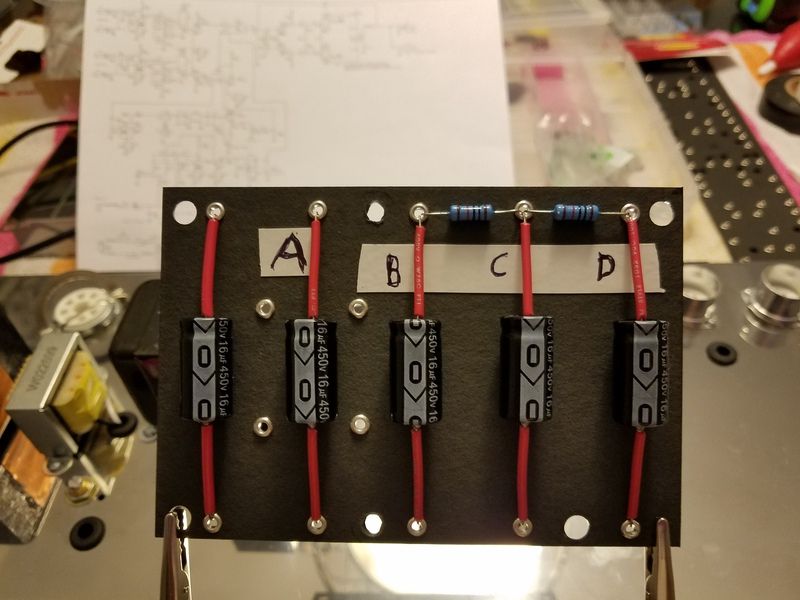
I started this late last night and just finished it up this morning. This is the filter cap board. These capacitors filter and smooth the rectified DC voltage to be usable by the rest of the amp in different areas. The little resistors are dropping resistors. They do what their name suggests - they drop voltage across the "nodes". The nodes (A,B,C, and D) are the points that feed the different areas of the amp.
And here we go with all the wires attached. "A" will filter the first blast of juice from the rectifier, pass through the standby switch, and supply power to the primary of the output transformer. Then through the choke and on to "B" where that still very high voltage will supply power to the power tube screens, the tremolo circuit, and reverb transformer. Then it gets dropped by the first dropping resistor and "C" will provide DC voltage to the phase inverter plates. And lastly, the voltage will get dropped again on to "D" where that last bit of voltage will move on to the plates in the preamp circuit. I went rogue a little and altered the black wires -the grounds. Nodes A, B, and C are high voltage with heavy currents. I want them to ground together at the power supply grounding point. Node D is much less intense and it's strictly preamp power supply, so I want it to ground at my ground rod with the rest of the preamp circuit. Hopefully I've done this right.

This is where the filter caps live and they will be covered by the doghouse. Right now I'm leaving it open because I'll need to test voltages in there. These are the notorious capacitors that will kill you....or at least shock the fucking shit out of you. These caps store electricity and you need to drain them before you go poking around inside of an amp. They need to be covered....but not right now.
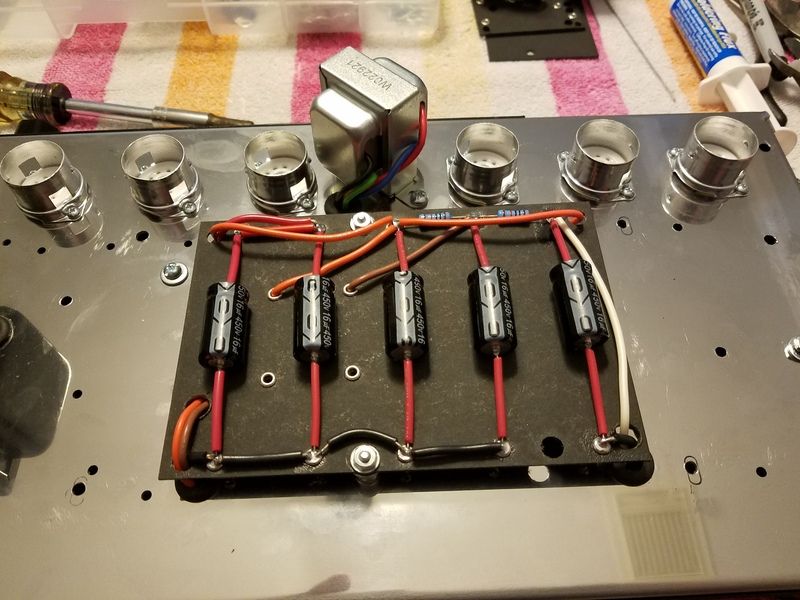
And what was previously a tidy and organized chassis is now a clusterfuck again. I left my wires pretty long. Lol. All of these wires will connect at various points on the board later. Red is my "A" wire. Orange is "B". Brown is "C". White is "D". Black is ground. Looks messy, but I know what's happening in there for now. Lol.

And with that done, it's finally time to populate the turret board and start making final connections.
I started this late last night and just finished it up this morning. This is the filter cap board. These capacitors filter and smooth the rectified DC voltage to be usable by the rest of the amp in different areas. The little resistors are dropping resistors. They do what their name suggests - they drop voltage across the "nodes". The nodes (A,B,C, and D) are the points that feed the different areas of the amp.

And here we go with all the wires attached. "A" will filter the first blast of juice from the rectifier, pass through the standby switch, and supply power to the primary of the output transformer. Then through the choke and on to "B" where that still very high voltage will supply power to the power tube screens, the tremolo circuit, and reverb transformer. Then it gets dropped by the first dropping resistor and "C" will provide DC voltage to the phase inverter plates. And lastly, the voltage will get dropped again on to "D" where that last bit of voltage will move on to the plates in the preamp circuit. I went rogue a little and altered the black wires -the grounds. Nodes A, B, and C are high voltage with heavy currents. I want them to ground together at the power supply grounding point. Node D is much less intense and it's strictly preamp power supply, so I want it to ground at my ground rod with the rest of the preamp circuit. Hopefully I've done this right.

This is where the filter caps live and they will be covered by the doghouse. Right now I'm leaving it open because I'll need to test voltages in there. These are the notorious capacitors that will kill you....or at least shock the fucking shit out of you. These caps store electricity and you need to drain them before you go poking around inside of an amp. They need to be covered....but not right now.

And what was previously a tidy and organized chassis is now a clusterfuck again. I left my wires pretty long. Lol. All of these wires will connect at various points on the board later. Red is my "A" wire. Orange is "B". Brown is "C". White is "D". Black is ground. Looks messy, but I know what's happening in there for now. Lol.

And with that done, it's finally time to populate the turret board and start making final connections.
Rebel Yell

