Let's build an amp! Greg's journey to electrocution

Re: Let's build an amp! Greg's journey to electrocution
Nice work so far. Impressive.

Re: Let's build an amp! Greg's journey to electrocution
At 1st glance I thought the light fitting was a component! Excellent deductive work Sherlock.
Cheers
rayc
rayc

Re: Let's build an amp! Greg's journey to electrocution
Thanks fellas. 
I'm gearing up to hopefully make some big progress today. I've come to a few realizations that aren't too troubling, but they alter my plan a little:
1) My multi-tap selector switch that should allow me to use 4, 8, or 16 ohm cabs from one single jack will not work. It's too big. It would fit fine in a Marshall chassis, but this Fender-type chassis is way too shallow. I'd have to file and grind the body of this switch down, and I don't want to compromise it's functionality. That thing is pretty important. So, my Plan B will be to wire two separate speaker jacks independently in their stock locations - one for 8 ohm, one for 16 ohm. The 4 ohm wire will just get capped off and not used. Or maybe I can locate a smaller selector switch.
2) I've not gotten to the turret board yet, but I've noticed that the board is supposed to be mounted with sheet metal screws? WTF? Lol. For all the niceness of this kit, they really dropped the ball on that part of the build. Sheet metal screws. That's some bullshit. So either on the exterior or underside, I'm going to have bare pointy screws sticking out into the air. Um, no. No way. I will either find or make my own standoffs from small bolts and bunch of lock nuts. No problem. Sheet metal screws. Bitch please. I don't do anything half-assed.
3) Far be it from me to question the good folks at Weber, but their layout suggests a pretty goofy way of wiring the power tubes. I don't pretend to know enough about why they decided to wire the tube sockets the way they did, but it's unnecessarily complicated and susceptible to noise. The original Fender AB763 circuit is not done exactly the way the Weber people specify, and I see no reason to do it the Weber way, so I will be wiring mine the Fender way. I'll explain it as I understand it if anyone wants to know.
So today I need to get some stand-off making materials, and some mounting loops to secure some wires to the chassis.
Rebel Yell
-
WhiskeyJack

- Site Admin
- Posts: 13134
- Joined: Sun Jan 12, 2014 11:48 pm
- Location: Canada
- Contact:
Re: Let's build an amp! Greg's journey to electrocution
Sick momentum greg, if it were me it would still be sitting in the box. Nice to see it coming together.
So if i am understanding all this correctly they literally gave you nothing to work off of? Just a electronic schematic and that's it?
So if i am understanding all this correctly they literally gave you nothing to work off of? Just a electronic schematic and that's it?

Re: Let's build an amp! Greg's journey to electrocution
I have a layout and a schematic. That's it. No instructions, no steps, no order of operation, nothing. I'm having to figure it out as I go. I'm doing it in chunks and using the google. So far I'm finding that if I break the amp down into it's separate functions and try to focus on just one little bit at a time, it hasn't been that bad. It's very intimidating to look at it as a whole amp with jillions of parts. But take it in pieces, like I only focused on the heater wiring at first, it wasn't bad at all. And I'm looking at it in layers. The heaters are a bitch, and they lie underneath everything, so naturally they had to be first. I don't wanna do that shit with other stuff in the way.WhiskeyJack wrote: ↑Thu May 03, 2018 1:08 pm Sick momentum greg, if it were me it would still be sitting in the box. Nice to see it coming together.
So if i am understanding all this correctly they literally gave you nothing to work off of? Just a electronic schematic and that's it?
So now I'm at the power section. Just power, nothing else. I'm not thinking about the pots or turret board or any of that shit. Just the power transformer and it's related connections. I've got to wire in the power cord, rectifier socket, pilot light, center taps, grounds, shit like that. Then that will be done and I'm on to something else.

Rebel Yell

Re: Let's build an amp! Greg's journey to electrocution
Looking good Gerg...Very interesting & will be a learning experience for us all... 

Gibson, Fender, Ibanez, Jackson
Ceriatone, Marshall, EVH
TC Electronic, MXR, Yamaha
My music @ Reverbnation

Re: Let's build an amp! Greg's journey to electrocution
Patience, logic and problem solving - impressive.
Cheers
rayc
rayc
Re: Let's build an amp! Greg's journey to electrocution
Thanks, it's been fun so far.
Thanks Ray. Let's hope the payoff is smoke-free.

Rebel Yell
Re: Let's build an amp! Greg's journey to electrocution
Didn't get to mess with it as much as I wanted to today. Every time I sat down to get started, some shit would happen that got in the way. Phone calls, doorbells, running around, bleh.
I did get a little of the power supply wiring done. The bundle of red wires on the left are unused and capped off.

The rectifier and main power plug.

Center taps ground and the blue wire will go to the fuse.

This is a mock up of one of the power tubes. The little resistor coming off pin 8 to ground is a 1 ohm 1% resistor. This makes reading and checking bias very simple. This will be part of my external bias test points that will be added later. The resistor spanning pins 1 and 5 will not stay like this. It will stay on pin 5, but the connection at pin 1 will be snipped and the wire that feeds it will be soldered directly to it.

So that was it for today.
Rebel Yell
Re: Let's build an amp! Greg's journey to electrocution
Lol. I caught a mistake already.
I was reveling in the luck and convenience of an open bolt hole right near my power socket to ground my mains power supply. See that little tiny green wire coming off the socket bolted to the chassis in the corner, nice and out of the way? Yeah that's a great spot to ground the power cable. Unfortunately for me, that hole already has a purpose - it's a mounting hole to mount the chassis in the head box. Lol. So.....yeah I'm gonna have to move that ground. No big deal. If this turns out to be one of my worst mistakes, I'll be happy.
I was reveling in the luck and convenience of an open bolt hole right near my power socket to ground my mains power supply. See that little tiny green wire coming off the socket bolted to the chassis in the corner, nice and out of the way? Yeah that's a great spot to ground the power cable. Unfortunately for me, that hole already has a purpose - it's a mounting hole to mount the chassis in the head box. Lol. So.....yeah I'm gonna have to move that ground. No big deal. If this turns out to be one of my worst mistakes, I'll be happy.
Rebel Yell
-
einstein magoo

- Posts: 412
- Joined: Sun Feb 26, 2017 3:05 pm
- Location: OHIO
Re: Let's build an amp! Greg's journey to electrocution
dumbfuck!
edit: forgot the lol.
edit: forgot the lol.
Re: Let's build an amp! Greg's journey to electrocution
lol pretty much. But I'm glad I caught it. Not that it would blow anything up. I'd just at the final put-it-all-together stage, all excited to button it up once and for all, and then.........doh!
Rebel Yell
Re: Let's build an amp! Greg's journey to electrocution
Awesome Greg...You should have that thing slapped together before long man, I'm excited to see & hear the results...
Gibson, Fender, Ibanez, Jackson
Ceriatone, Marshall, EVH
TC Electronic, MXR, Yamaha
My music @ Reverbnation
Re: Let's build an amp! Greg's journey to electrocution
Thanks. I'm brainstorming some ideas for the rear panel right now. I want to move everything over one spot so I can get back to trying to use this gigantic impedance selector switch. I'll have to re-label the rear panel, which doesn't matter to me, but I'm worried about introducing noise since everything is pretty crammed back there. I don't think it will be a problem, but I guess we'll see.......
Rebel Yell
Re: Let's build an amp! Greg's journey to electrocution
Man, I think it's fuckin' great you're doing this...We've all followed each other's tone chase for years now, & even after years of this madness, it's still a rush for me...Greg_L wrote: ↑Fri May 04, 2018 1:45 pm Thanks. I'm brainstorming some ideas for the rear panel right now. I want to move everything over one spot so I can get back to trying to use this gigantic impedance selector switch. I'll have to re-label the rear panel, which doesn't matter to me, but I'm worried about introducing noise since everything is pretty crammed back there. I don't think it will be a problem, but I guess we'll see.......
You've came to a point in the road where you're actually taking the wheel & making your own road, instead of just traveling along someone else's...I'm actually very impressed with your skills dude, & all of you guys here are a great inspiration to me...
Very, very cool man...
Gibson, Fender, Ibanez, Jackson
Ceriatone, Marshall, EVH
TC Electronic, MXR, Yamaha
My music @ Reverbnation
Re: Let's build an amp! Greg's journey to electrocution
Well, there's the point. I'd have carried on and not noticed then have had to pull the entire thing apart to reground because my brain doesn't do the logic, sensible, schematic flow thing.
Cheers
rayc
rayc
Re: Let's build an amp! Greg's journey to electrocution
Minerman wrote: ↑Fri May 04, 2018 2:01 pm
Man, I think it's fuckin' great you're doing this...We've all followed each other's tone chase for years now, & even after years of this madness, it's still a rush for me...
You've came to a point in the road where you're actually taking the wheel & making your own road, instead of just traveling along someone else's...I'm actually very impressed with your skills dude, & all of you guys here are a great inspiration to me...
Very, very cool man...
Thanks dudes. My idea of moving the controls on the back panel over one slot to make room for other things is going to work! So I'll be working on that tomorrow.
Rebel Yell

Re: Let's build an amp! Greg's journey to electrocution
Still watching... This is uber cool gerg..
Re: Let's build an amp! Greg's journey to electrocution
Thanks.
I don't think I'll get to it much today. I'm gonna go on one of my music store runs and finger bang all sorts of gear today. I'll be gone most of the day.
One thing I did do this morning though, and it's very important, is fucking clean up. Lol. Man I had shit everywhere. So much for being meticulous and clean. My immediate work area is organized, but the bits of wire and insulation and solder blobs and just general empty boxes and packaging and shit floating in the orbit of my work area was expanding and starting to catch the eye of the missus. Can't have that. Lol. So I cleaned up and reorganized. We're good to go again.
Rebel Yell
Re: Let's build an amp! Greg's journey to electrocution
Did a little amp work today. I'm starting to think about where the board is going to go, and how tall I'll need to make my standoffs. Where am I going to run my ground buss? Where the hell is the bias pot going to go? Before I can do any of that, I need to finish the power wiring, and do it in a way that is less risky for electrocution.
The "Fender way" could shock the hell out of me even with a blown fuse or some other failed component because the wall power goes to the switch first, which is just crazy dumb. So I modified the routing. I'm going....
Wall hot to fuse tip
Fuse tip to fuse shell
Fuse shell to power switch
Power switch to power transformer.
This way, the fuse sees juice first, and can protect everything else like a fucking fuse is supposed to.
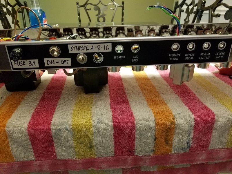
But even before we do that...let's move the fuse holder closer to the power supply....and everything else over with it. This is my new rear panel layout that I talked about earlier. Looks ghetto and totally DIY and I fucking love it.
Now we can finish wiring the power supply.
First I had to fix my little error and move the mains power ground. New hole drilled, no problem.
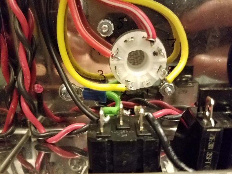
Fuse holder tip connected and sealed in shrink tubing. That tip is hot, and we don't ever wanna touch it. From there we go to that little sideways switch next to it, and the blue wire runs power back to the PT.
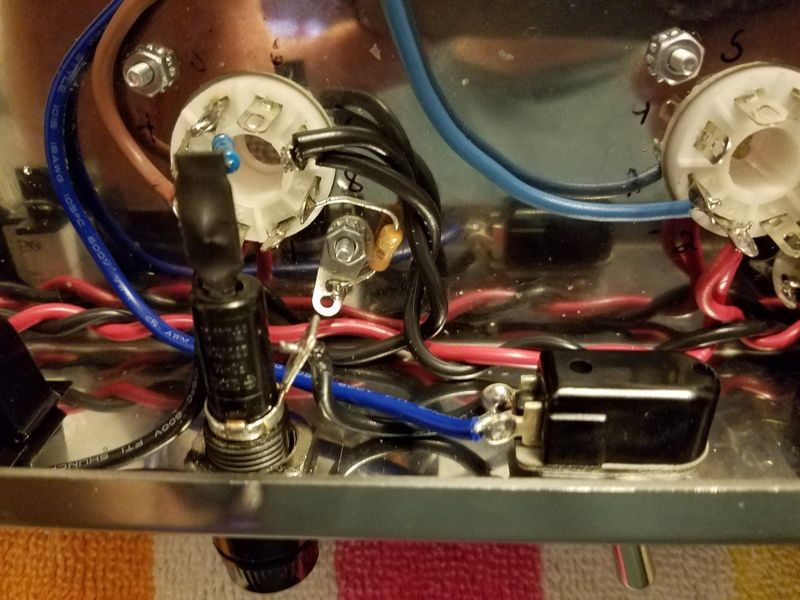
While we're down there, one of the "lower layers" of the wiring are the output transformer primary wires. They are the blue, brown, and red wires coming off the OT. We don't need the red wire yet, but the blue and brown wires go to pin 3 on each power tube. A very common error is to get these reversed, which yields a deafening squeal at startup....and looking at my OT schematic, I think I've done just that. I'm gonna research and verify it. The fix is simple - just reverse the wires. Swap blue and brown on each tube. I left enough slack in anticipation for this problem.
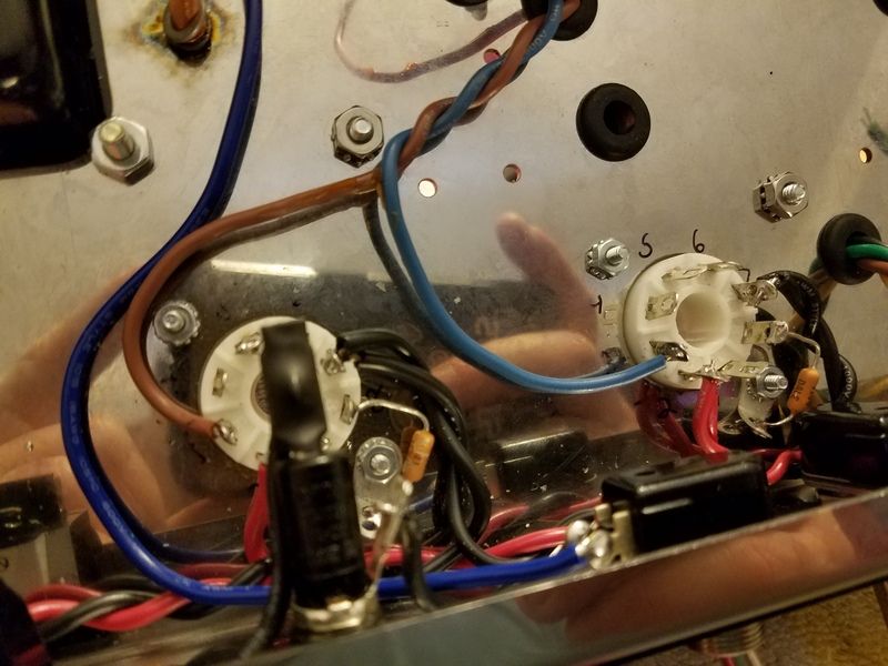
Moving on....the last major section of the power supply side of the amp is the "bias board" and pot. The pot mounts to the chassis and the bias board tucks way up in a virtually impossible to reach portion of the chassis. Problem - there is no hole to mount the bias pot. This chassis is full of holes, and none of them are for a the bias pot. No big deal. Time to drill again.
This looks like a good enough spot for a pot. Boom. It rhymes. The main board is just dropped in it's general location to see how the pot is gonna fit with everything else.
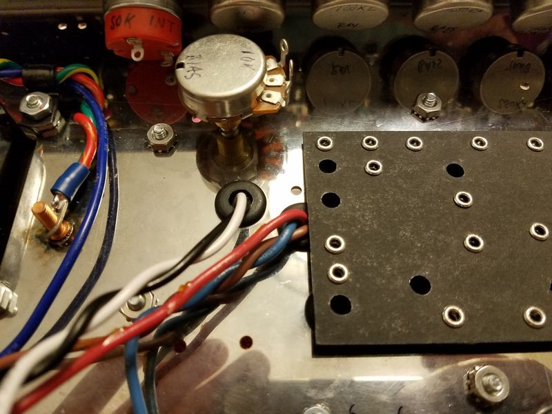
X marks the pot spot. Damn I'm killing it today.
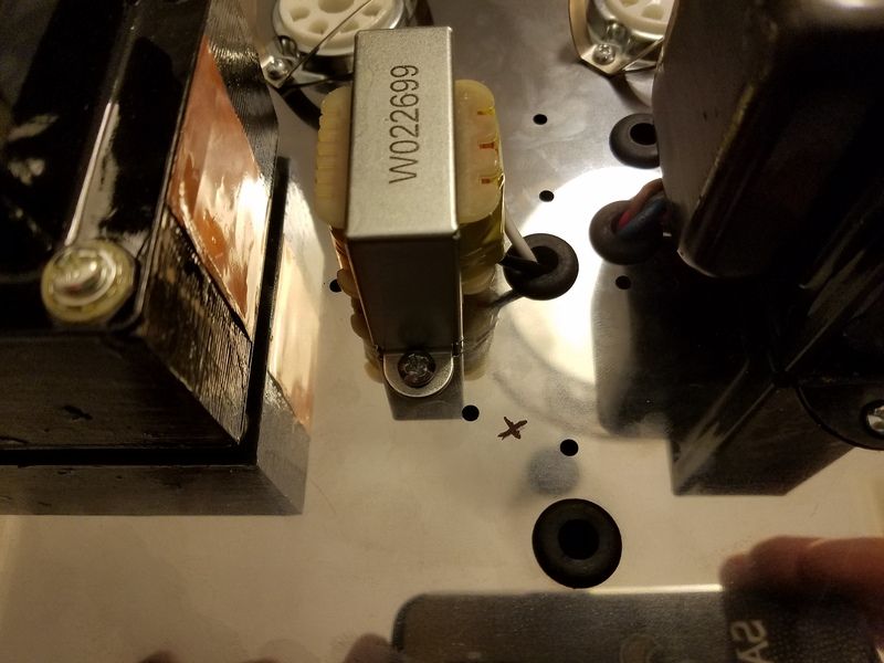
Big ass hole.
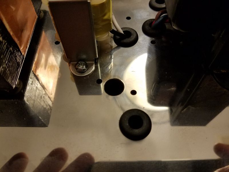
Fuck we gotta clean this up.
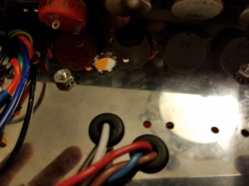
I may be a little biased but that bias pot is in the right spot!
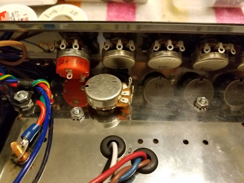
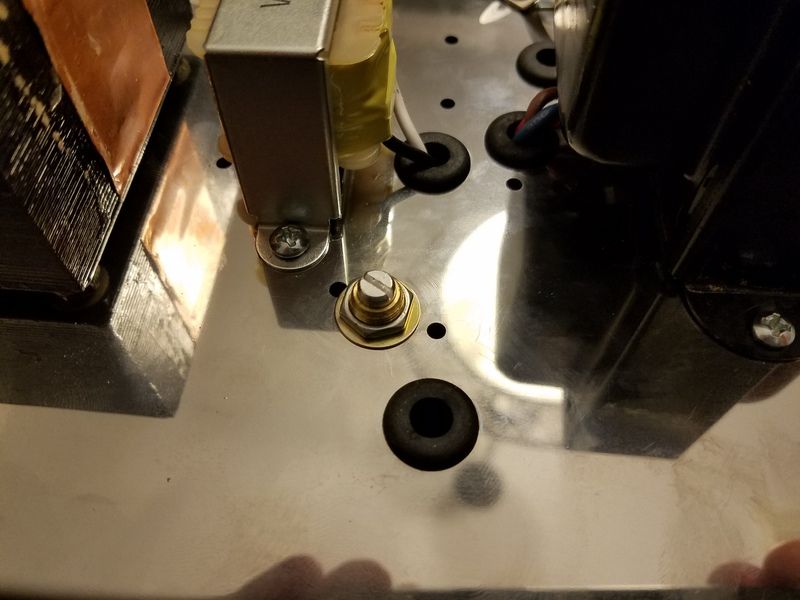
Okay enough with the shitty puns and rhymes. This is the creepy cranny the bias board has to go into - that little dark corner between the pilot light and tremolo pot. Thankfully there is actually a damn mounting hole in there.
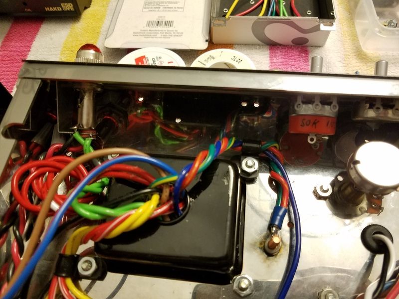
And this little fucker is the bias board. This will be the first board that we'll start populating with caps and resistors. And the final PT wire that we need to use will attach to this board. This will supply the bias voltage that we will need to keep the power tubes alive.
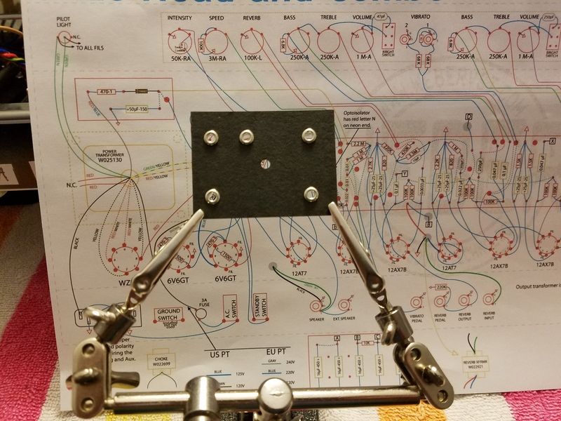
So I guess next up will be that little bias board.
The "Fender way" could shock the hell out of me even with a blown fuse or some other failed component because the wall power goes to the switch first, which is just crazy dumb. So I modified the routing. I'm going....
Wall hot to fuse tip
Fuse tip to fuse shell
Fuse shell to power switch
Power switch to power transformer.
This way, the fuse sees juice first, and can protect everything else like a fucking fuse is supposed to.
But even before we do that...let's move the fuse holder closer to the power supply....and everything else over with it. This is my new rear panel layout that I talked about earlier. Looks ghetto and totally DIY and I fucking love it.

Now we can finish wiring the power supply.
First I had to fix my little error and move the mains power ground. New hole drilled, no problem.

Fuse holder tip connected and sealed in shrink tubing. That tip is hot, and we don't ever wanna touch it. From there we go to that little sideways switch next to it, and the blue wire runs power back to the PT.

While we're down there, one of the "lower layers" of the wiring are the output transformer primary wires. They are the blue, brown, and red wires coming off the OT. We don't need the red wire yet, but the blue and brown wires go to pin 3 on each power tube. A very common error is to get these reversed, which yields a deafening squeal at startup....and looking at my OT schematic, I think I've done just that. I'm gonna research and verify it. The fix is simple - just reverse the wires. Swap blue and brown on each tube. I left enough slack in anticipation for this problem.

Moving on....the last major section of the power supply side of the amp is the "bias board" and pot. The pot mounts to the chassis and the bias board tucks way up in a virtually impossible to reach portion of the chassis. Problem - there is no hole to mount the bias pot. This chassis is full of holes, and none of them are for a the bias pot. No big deal. Time to drill again.
This looks like a good enough spot for a pot. Boom. It rhymes. The main board is just dropped in it's general location to see how the pot is gonna fit with everything else.

X marks the pot spot. Damn I'm killing it today.

Big ass hole.

Fuck we gotta clean this up.

I may be a little biased but that bias pot is in the right spot!


Okay enough with the shitty puns and rhymes. This is the creepy cranny the bias board has to go into - that little dark corner between the pilot light and tremolo pot. Thankfully there is actually a damn mounting hole in there.

And this little fucker is the bias board. This will be the first board that we'll start populating with caps and resistors. And the final PT wire that we need to use will attach to this board. This will supply the bias voltage that we will need to keep the power tubes alive.

So I guess next up will be that little bias board.
Rebel Yell